Turbulation Troubleshooting Guide
Streakiness is typically found in motion picture photography in scenes having large areas of static uniform density such as skies, sand and interior/exterior walls. Although streakiness can be introduced during film manufacturing operations, it is usually introduced as a consequence of non standard film processing conditions. Retained silver, retained silver halide, processing scum, pressure induced sensitivity and developer nonuniformity are all examples of process induced streakiness.
For purposes of this discussion we will deal only with developer nonuniformity caused by inadequate developer turbulation. Our goal here is to provide the framework for problem solving relative to ECN2 processing machines, but similar principles may be applied to print machines as well. The discussion is centered on machines employing drilled header turbulation designs.
It is important to note that density nonuniformity occurs on all camera negative and ECI films when developer turbulation is inadequate. Module 2 of the H24 Processing Manual, published by Kodak, provides design guidelines for turbulation systems, and these guidelines must be followed rigorously for best results. ALL guidelines must be met simultaneously to insure satisfactory tubulation for motion picture films. These guidelines include:
- Five or more hole per inch
- Hole size of at least 0.031 inches
- 0-20 psig in the drilled header
- 1.0-1.5 second spray pass frequency
- Hole -to-film distance of 1/4-1/2 inches
- Flow per hole of 250 ml/min 10 psig and 350 ml/min 20 psig and a total flow of 325-450 liters/minute, depending on the number of 0.031 inch holes and pressure.
When developer induced streaks are produced in processing machines, it is important to take steps to determine probable cause. A thorough review of the turbulation system must quickly be made. A cursory look at the system will indicate if the holes are plugged, if the pumps are turned on and if the holes are aimed toward the film. Additional effort is needed to determine the hole size, hole spacing and vertical distance between turbulator bars. The distance between bars can be used in combination with the machine speed to calculate the spray pass frequency- the time it takes to pass between two bars, which should equal 1-1.5 sec.. The size of the holes, the total number of holes and the total flow output of the pump must also be determined. Measurements of pressure in the drilled header are useful but are sometimes unavailable, and by themselves are not necessarily good indicators. For example, pressure increases as the holes become plugged; this reduces turbulation and produces nonuniformity. Determinations of flow per hole are made by simply dividing the total flow from the pump by the total number of holes. Keep in mind that this assumes all holes within the system are a common size.
Frequent equipment mistakes we've observed include:
- Holes that are too large and pumps that are too small
- Too many holes for a given size pump
- Holes that are misdirected away from the film
- Too few holes per inch
- Different size holes within a single turbulation system
- Turbulator bars that are too far from the film
- Turbulator bars that are too far apart vertically, or missing altogether.

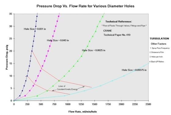
Figure 1 of the attachment shows the relationship between pressure drop (pressure in the header) and flow rate per hole, for various diameter holes. This graph was based on calculations using fluid flow equations found in the literature: Crane Technical Paper No. 310, "Flow of Fluids Through Valves, Fittings and Pipe", Equation 2-23. As noted earlier, the H24 manual states that the hole size should be at least 0.031 inches in diameter, and pressure in the header for this size hole should be 10- 20 psig. The flow rate required to maintain 10 psig in the header using an 0.031 inch hole is 250 ml/min/hole; to maintain 20 psig the flow rate is 350 ml/min/hole.
What about larger diameter holes? Larger holes are commonly used in turbulation designs to provide protection against hole plugging. Figure 1 shows the profound effect of hole size on the flow rate needed to maintain pressure in the header. For example, a sizeable flow rate of over 2000 ml/min/hole is needed to maintain a pressure of 10 psig when using a 0.09375 inch hole. This is a consequence of the disproportionately large increase in the area of the hole when the diameter is increased. The area of the hole increases by a factor of 9 when the diameter of the hole is increased by a factor of 3. Given that an entire turbulation system could include several hundred holes, the use of larger hole sizes has serious implications on pump size, all other things being equal.
Is a pressure of 10 psig needed with a larger hole? Lines of constant kinetic energy are shown in Figure 1 for the upper and lower limits of pressure for various hole sizes. The upper and lower lines are themselves different in kinetic energy, but from point to point along an individual line they are the same. For example, looking at the lower line, the same kinetic energy is delivered using 250 ml/min/hole with an 0.031 inch hole, 380 ml/min/hole using an 0.043 inch hole, 630 ml/min/hole using a 0.0625 inch hole and 1070 ml/min/hole using an 0.09375 inch hole. Similar numbers can be established from the graph for the higher pressure constant kinetic energy line. In both cases kinetic energy of the 0.031 sized hole was used as the reference at 10 and 20 psig respectively.
Note that at constant kinetic energy , pressure decreases as the hole size increases . The concept of using lower pressure with larger holes has beneficial implications on pump size. In addition, it is possible that because of larger plumes and higher coverage associated with larger holes, adequate turbulation may be achieved with fewer than five holes per inch when larger holes are used. This would mean fewer holes in the total system, and reduced pump requirements. These aspects of turbulation design is under study. Note from Figure 1 that the upper and lower lines of constant kinetic energy may be used to describe the acceptable window for machine operation for different diameter holes.
Although there is some practical data from field machines as well as limited modelling to support the constant kinetic energy theory, the approach still needs to be validated in practice. The conditions described are all untested and should not be used until verified with a photographic tests. Pilot designs should be tested using precision flashed film, which Kodak will be happy to provide and analyse. It may be mentioned that practical testing has been accomplished using 0.031 inch holes and validated in 16, 35 and 65 mm formats.

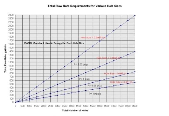
Figure 2 shows the total flow requirements for various diameter holes for entire turbulation systems containing several hundred holes; the plots are based on constant kinetic energy. A typical 35 machine running at 100 feet per minute might utilize 1500- 2000 holes and should use a 100-120 gal/minute pump with 0.031 inch holes, and a 400-500 gallon per minute pump with 0.09375 inch holes. A typical 65 mm machine running at 100 feet per minute might utilize 3000 holes and would require a pump delivering 200 gallons per minute using 0.031 inch holes and 800 gallons per minute using 0.09375 inch holes.

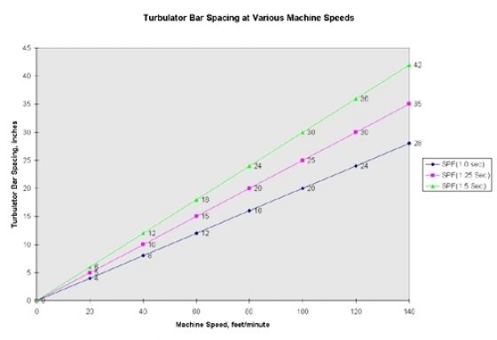
Figure 3 shows the turbulator bar spacing requirements at various machine speeds needed to meet the recommended range for spray pass frequency (SPF). The H24 manual states that the spray pass frequency should be between 1-1.5 seconds. Increasing the machine speed permits increased bar spacing to achieve recommended goals. From Figure 3 it is apparent that the bars should be 8-12 inches apart for a machine running at 40 feet per minute and 20-30 inches apart for a machine running 100 feet per minute. When the bars are further apart, the spray pass frequency is excessive and inadequate turbulation will result.
Additional Comments:
Backup rollers are needed to make certain the desired spacing between the turbulation bar and the film plane is maintained during processing. Backup rollers must be used at impingement points, or the film will be displaced away from the turbulation bar and solution velocity at the film surface will be reduced. This produces nonuniformity of the developed image.
Routine maintenance of the turbulation system is necessary to make sure the holes are always clean and that the equipment is operating properly.
Summary:
Module 2 of the H24 manual specifies design parameters for turbulation systems for ECN2. These parameters have been found in practice to provide excellent uniformity in all film formats. For new machines using drilled headers we generally recommend the use of 0.031 size holes as the best starting position, for pump size considerations as well as film quality. If hole plugging is a concern, a Y- strainer can be installed in the delivery line prior to the turbulation system for ease of maintenance. In severe cases the holes can be drilled out to larger diameters and the pump resized if necessary.
Final Note:
WTS will help any customer who has a concern about turbulation or machine set up. We will provide film test samples to check the uniformity produced in individual machines, and we will be happy to provide consultation with respect to equipment retrofits.